Free small package shipping on orders above $249.99
Interactive Wheel Loader Diagram: Search and Learn About Wheel Loaders
Sign In
Registered Customers
No account?
Having a customer account enables faster checkout, order tracking online, and (if you want) emails about specials and events.
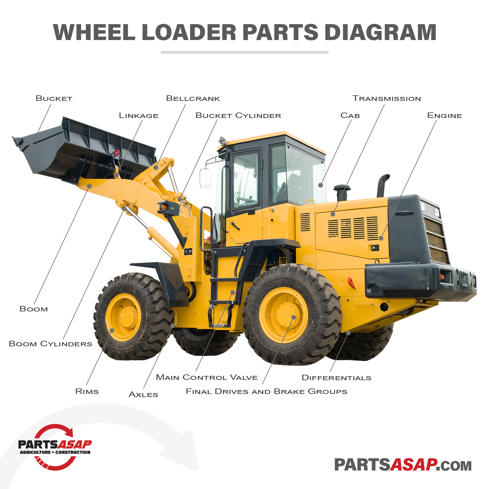
While most people understand the purpose and the unique capabilities of a wheel loader, many might still wonder how every part on the machine works together or what the name of each part is. For those readers, we’ve put together this simple interactive wheel loader diagram. Whether you’re a wheel loader wizard or you’re just an interested construction site onlooker, hopefully it will help you better understand this important machine.
Buckets / Attachments
Buckets are the most common type of attachment on a wheel loader, but even buckets come in a wide range of sizes and designs to accommodate different materials and different working conditions. From rock buckets in mining to grapple buckets in forestry, a wheel loader can operate as a multi-purpose workhorse with a quick change of the bucket. Beyond buckets, forks and plows are common attachments for wheel loaders.
Boom
The boom connects the wheel loader’s bucket (or other attachment) to the body of the wheel loader. The boom must be built to accommodate heavy loads, resistance during pushes, and constant and repetitive use. The length of the boom defines the reach of the wheel loader and the dumping height of the bucket. A boom that is too short can create issues in loading large equipment or piling materials above a certain height.
Boom Cylinders
Two hydraulic cylinders, one on each side of the boom, control the lifting and lowering of the boom. These cylinders must be sufficiently powerful to lift heavy loads and designed for frequent use. A wheel loader operator must take care to prevent damage to boom cylinders during lifts and when the boom is subject to forces from the side.
Linkage
The links on a wheel loader connect pivoting parts together through the use of pins. While they may seem basic, their length, the number of links, and their design define how the bucket will move and tilt as cylinders are engaged. In a wheel loader with a typical Z-bar linkage, an operator must precisely control both the bucket cylinder and boom cylinders when raising or lowering the bucket if it must remain level.
Bellcrank
Connecting the boom, bucket cylinder, and bucket (through a link) is a heavy-duty bellcrank. This part allows the operator to tilt the bucket and acts as a simple lever as it pivots at its center.
Bucket Cylinder
In the center of the wheel loader boom, a heavy-duty hydraulic cylinder connects the wheel loader to the bellcrank and, in turn, to the bucket. Because of the configuration of the bellcrank and linkage, extending the cylinder allows the operator to tilt the bucket towards themselves in a scooping motion, while retracting the cylinder allows the operator to tilt the bucket away from the cab in a dumping motion.
Rims and Tires
Wheel loaders operate in a wide range of ground conditions and, as such, must be designed to accommodate the specifics of the work surfaces. Substantial rims must be designed to hold the considerable weight of many wheel loaders along with the weight of loads they are carrying. Tires must be designed to provide traction in non-paved environments, avoid damage from rough materials, and even prevent over-impacting or harshly compacting surface areas.
Axles
A substantial front and rear axle on the wheel loader connect the drive systems of the wheel loader to the wheels. Since a wheel loader can experience heavy impacts from below, axle shafts and internal gears inside the axle require an especially tough and robust axle housing.
Differentials
Front and rear differentials in a wheel loader sit at the center of the axles and transform the direction of power while also utilizing a geared system to allow wheels on the same axle to turn at different speeds in specific conditions, like when rounding a corner.
Final Drives and Brake Groups
Final drives and brake groups are incorporated into the axles of the wheel loader. Final drives consist of a number of planetary gear systems and are the last point for converting power into high torque output as it is transferred to the wheels.
Transmission
The transmission on a wheel loader utilizes the principles of gear ratios to allow the machine to perform at various speeds and at different levels of torque as power is transferred from the engine, through the transmission, and eventually to the wheels. While a 4-speed transmission is common, other variations allow for customization for working conditions like when long, repetitive traveling is required. For most wheel loaders, a transmission will utilize a torque convertor, but the use of a hydrostatic transmission is also possible.
Engine
At the heart of the wheel loader is an internal combustion engine that turns fuel into output to power the machine’s drive system, hydraulic systems, and other systems. Wheel loader engines are specifically designed to meet target goals for durability, efficiency, and reliability during operation of the loader and to maintain proper workability under harsh or even extreme working conditions.
Main Control Valve
The main control valve in a wheel loader controls the direction of flow and pressure of the hydraulic system and each of the loader’s hydraulically-powered parts.
Cab
The cab on a wheel loader operates as a central command station for a wheel loader. Due to the environments they work in, the cabs on wheel loaders are often reinforced with safety equipment and, in designing the cab and how it is incorporated into the machine, a focus is placed on ensuring an operator has clear lines of sight and unobstructed views while operating the machine. Increasingly, a wheel loader cab is also home to a vast array of intelligent equipment to help an operator perform their work, monitor their efficiency, and remain vigilant of their surroundings.
At first glance, a wheel loader might seem like a simple machine, but if you stop and watch one in action, you’ll often notice how its unique design — especially under the control of an expert operator — ensures its position as a staple on a worksite.
If you’ve arrived here in search of a parts solution for your wheel loader, our Parts Specialists are always here to help. As a top dismantler of wheel loaders, our inventory is hard to match and with connections to our vast interconnected parts network, a solution to your parts problems is often simply a call away. Just drop us a line or request a quote.