Free small package shipping on orders above $249.99
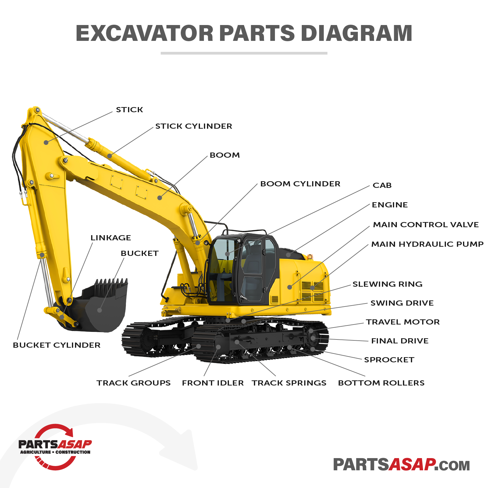
Interactive Excavator Diagram: Search and Learn About Excavators
Sign In
Registered Customers
No account?
Having a customer account enables faster checkout, order tracking online, and (if you want) emails about specials and events.
Whether you’re a passionate skid steer specialist, you’re a compact track loader operator looking for more knowledge on your machine, or you’re just about to roll up your sleeves and take on a skid steer repair, we’ve created this simple interactive skid steer diagram to help you better understand this important construction machine.
Cab
The excavator’s cab is the central control station for the excavator’s operator. In the cab, an operator will have controls for both the movement of the excavator and the manipulation of the arm and attachments of the excavator. Pedals, levers, and joysticks are used in (often complex) combinations to control the excavator. In modern excavators, control and measurement will be augmented with touchscreens, displays, and other forms of feedback and input in the cab.
Boom
The boom is a part of the arm and is directly attached to the excavator’s house. The length of the boom and the stick define the reach and digging depth of an excavator. Knuckled booms offer side-to-side movement of the arm, hinged booms are divided booms that allow for a new point of articulation, and long reach booms create the ability to extend the area with which an excavator can interact without moving the machine.
Boom Cylinder
The boom is controlled by hydraulic cylinders pinned to the house and the boom. By extending and contracting the cylinder rods from the cylinder housing the operator is able to lift and lower the boom.
Stick
A part of the excavator’s arm, the stick sits between the boom and the attachments. The far end of the stick incorporates a system for connecting to attachments and allowing for their control from the cab. An excavator could employ a longer stick for added reach or a shorter stick for increased digging power.
Stick Cylinder
The excavator’s stick is controlled by a hydraulic cylinder connected to the boom and the stick. Extending and contracting the stick cylinder will pivot the attachment towards or away from the machine and the operator.
Bucket / Attachments
Buckets are the most common type of attachments on an excavator, but excavators today utilize a wide range of attachments for digging, moving items, or interacting with materials in numerous ways.
Bucket Cylinder
The bucket cylinder controls the action of the bucket and is connected to the stick and the bucket. By extending or retracting the cylinder, the operator can control the attachment. In the case of a bucket, extending the cylinder will initiate a scooping movement and retracting the cylinder will dump the bucket.
Linkage
Linkage (or simply links) are heavy-duty, metal bars that connect attachments (and other parts) to the stick through the use of pins that allow for movement in specific directions.
Engine
At its most simple, the engine on an excavator converts energy (generally from diesel fuel) into motion. The engine powers all parts of the machine through the direct output of energy to moving parts, energy conversion to electric parts, or often to output through the hydraulic system.
Main Hydraulic Pump
The main hydraulic pump on an excavator transforms mechanical energy from the engine into hydraulic energy that is in turn supplied to hydraulic components through hydraulic fluid. Cylinders, travel motors, swing motors, and other hydraulically-powered components all derive their power from hydraulic pumps on the excavator.
Main Control Valve
By controlling the pressure and direction of hydraulic fluid a hydraulic valve is able to finely dictate a machine’s movements and the movements of its attachments. Due to the complexity of a hydraulic system on an excavator, the main control valve is often a complex labyrinth of chambers and connections for the movement of hydraulic fluid and the exchange of energy.
Slewing Ring
The slewing ring (or slewing ring bearing, turntable bearing, slewing gear) is a horizontally mounted bearing with an attached gear. The bearing connects the upper house with the lower undercarriage and allows each to move separately and, in turn, for the house to spin freely of the undercarriage.
Swing Drive
The swing drive is directly mounted to the house and consists of a swing motor and a swing gearbox. Energy is converted into high torque output through a gear system and output through a geared shaft that engages with teeth in the slewing ring. Turning of the swing drive shaft results in movement along the path defined by the slewing ring.
Travel Motor
Located in the undercarriage at the back end of the excavator’s tracks, the hydraulic travel motor is paired with a final drive gear box and powers the movement of the tracks.
Final Drive
On an excavator, a final drive transfers power from the drive train to the tracks using a system of gears designed to reduce speed and increase torque. Most commonly, a final drive is divided into a hydraulic travel motor and a gearbox with gears designed to increase torque as it is applied to the tracks.
Sprocket
The sprocket is a cogwheel with teeth that connects into and interacts with segments in the excavator’s track. As the sprocket rotates it advances the track and propels the excavator forwards or backwards by pulling the track in a direction.
Front Idler
The front idler on an excavator is a large wheel at the front of the track group that guides the track along its path and, in conjunction with the track springs, sets the tension of the track.
Track Springs
Track springs (or recoil springs) are large springs designed to absorb impacts and ensure the track is properly tensioned. Most track springs work in conjunction with a grease cylinder to set track tension.
Bottom Rollers
An excavator has a number of short, rolling cylinders designed to carry the weight of the excavator and to guide the track along its path. These rollers are located inside the track and at the bottom of the undercarriage.
Track Groups
Excavators are commonly used in a wide-range of ground conditions and must be able to both move in low-traction locations and remain firm and balanced while stationary. The tracks on an excavator are designed to provide ample grip and maneuverability. Tracks can be either metal, rubber, or hybrid. The roughness and pattern of tracks is designed to match the work surface where the excavator will perform its work. While tracks are still most common, increasingly some excavators employ wheels to allow for faster transport and less wear on delicate surfaces like city streets.
We hope you found this diagram and these simple, short definitions helpful in your excavator knowledge search. As always, if you're searching for a part solution for your own excavator, our expert Parts Specialists are here to help connect you to a part in our deep and ever-expanding inventory or even to search our vast parts network. Just drop us a line or request a quote.